


Blog 6: Project Development👨👩👧👧☣️
- Valarie Goh
- Feb 19, 2023
- 5 min read

Updated: Feb 19, 2023

Yo sup everyone! 🤟 I am back with another blog for CPDD woohoo!🥳So today I will be my last time sharing my journey in CPDD with you. So let's kick off with the Project Development phase and I hope yall will learn something from it woohoo! 😉
In this blog, I will:
Briefly describe my team chemical device
Show how the team planned, allocated the tasks, and executed the project.
Document the entire design and build process of the chemical device and include videos, pictures, and screen captures of the processes.
Include “Hero shot” of every milestone of the processes, example the part A that was 3D printed, part B that was laser-cut, electronics components moved/worked according to the program. Hero-shot is taken with the person-in-charge holding/working/making the parts.
Include the name of the person who was in-charge of every part of the project.
Document my individual contribution to this project.
Provide the link to the page of the blog of my teammates.
Describe problems encountered and how the team solved them.
Include all the project design files as downloadable files.
Embed the final prototype design file, i.e., the final fusion360 design file showing the entire prototype.
Type my Learning reflection on the overall project development.
Our team Chemical Device

My team has made a prototype of a fume extractor. As you can see on the right, the front side of the prototype is the sensor with a "window" at the side. The purpose of the "window" is to absorb the soldering fumes and thus the fan will blow it out into the atmosphere after filtering it.

As you can see on the left, on the back of the device, there is a fan that has a filter installed on top of it to filter out the soldering fumes particles. It is angled in such a way as to prevent the fumes from blowing to any individual that is facing in front of the fan. At the side of it is the wirings of the servo, sensor, and Arduino board that is covered with a transparent cover of our team logo.

The purpose of the servo is an indication to let others know that soldering is occurring and thus there is a flag attached to it that I will talk more about it below. The flag at the side is attached to the servo. When it senses fumes, the fan will turn on and the flag will rise up. However, when there are no fumes, the fan is off and the flag went go down

Users need the fume extractor to remove the soldering fumes because of the harmful gases such as lead oxide that it gives out. This will ensure the safety of the user example students and lecturers when they do solder during their practical lessons. It is important to solve as it aims to reduce the number of hazards and dangers that workers encounter while doing these tasks.
Team Planning, allocation, and execution

My Team Members
Names | Goh Kai Xuan Valarie😆 | Mohamed Asraf Bin Abdul Rahman😎 | Nur Insyirah Binte Azmi🤗 | Eshvin Kaur Chahal😂 |
|---|---|---|---|---|
Roles | CEO | COO | CFO | CSO |
 |  |  |  | |
Allocated Task | Fabrication and coding, video (Combine both codes) | Design of prototype and coding (Exhaust Fan & Servo) | Buying of material, assembly of prototype | Clean-up of fabrication and design of logo and flag |

BOM
The table is shown to be the finalized BOM (BILL OF MATERIALS) table.

Link to BOM:
Ghant Chart
The table below is our group finalized Gantt chart (planned and actual) and the task allocation for each team member.

Link to Gantt Chart:
3. Design and Build Process
In this section, I will provide documentation of the design and build process.
3D Print | Laser Cutting | Mechanism | Exhaust Fan | Jumper Wire | Arduino Uno and Blackboard |
|---|---|---|---|---|---|
 |  |  |  |  |  |
In-charge: Valarie | In-charge: Valarie | In-charge: Eshvin | In-charge: Insyirah | In-charge: Asraf | In-charge: Asraf |
Part 1. Design of prototype and coding for exhaust fan and servo (done by Asraf). Link it to Asraf’s blog
Documentation for task 1.
Hero shot for task 1.
Part 2. Fabrication and Combining Coding for the prototype (done by Me, Valarie). Link it to Valarie blog
Documentation for task 2.
I am in charge of doing fabrication, combing coding, and designing the process video. Firstly, I will explain the fabrication which is about 3D printing and Laser Cutting.
So, firstly with my group, we discuss the design and the structure of the whole prototype. With that, Asraf will sketch 2D in Fusion 360 and after he is done he will send me the f3d/stl file and dxf/svg file for 3D printing or Laser Cutting. Then I will collate everything in one thumb drive so that is easier for me to just go to the printer or cutting station to do my prototype.
Device Name | Device Picture | What we print |
|---|---|---|
Original Prusa i3 MK3S+ 3D printer (my friend house) |  |  |
LC-EpilogPro-11 (T11C) |  |  |
LC-Universal660-14 (T14) |  | 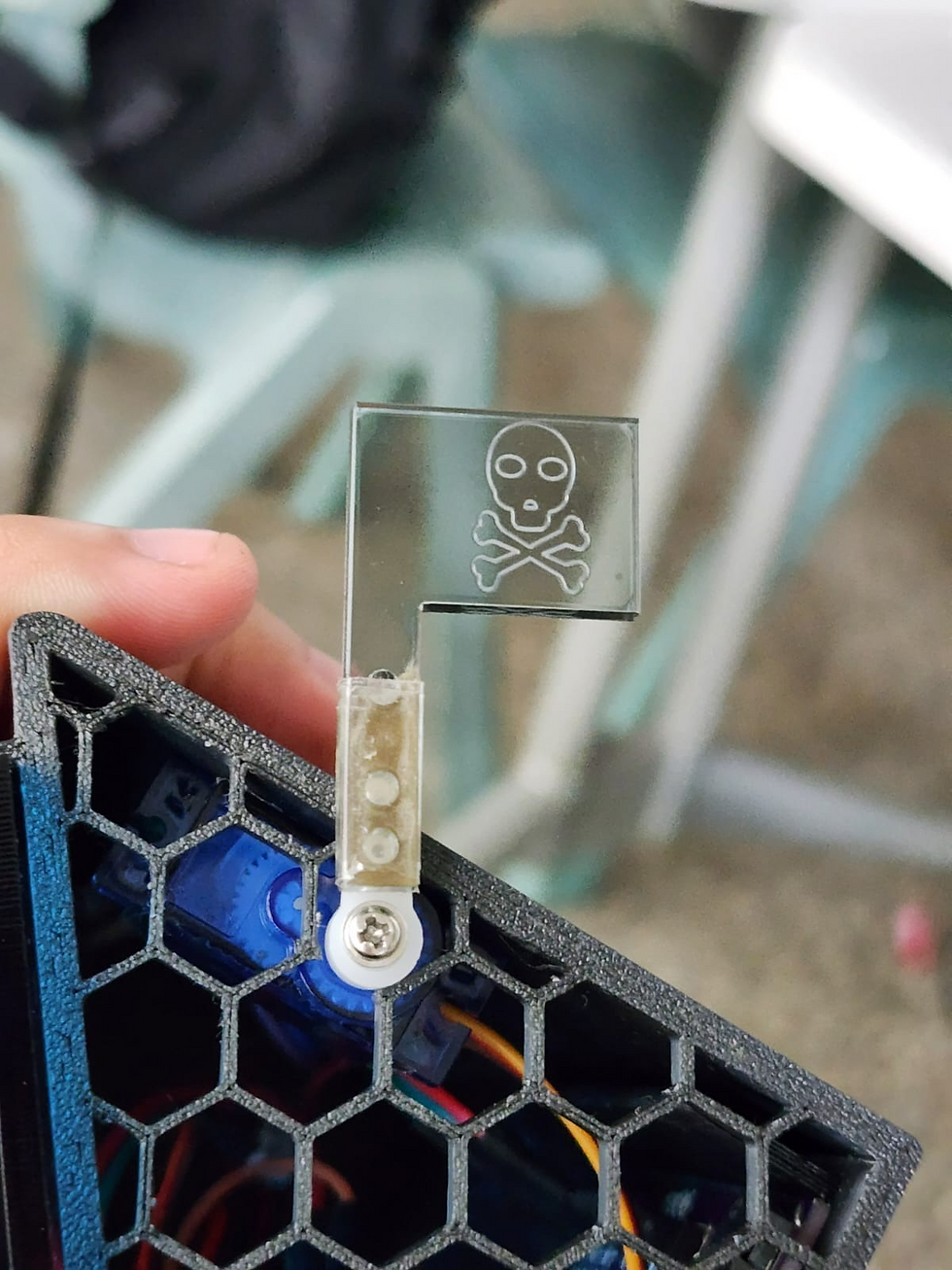 |
For 3D printing:
Things we faced during the printing time:
Problem faced | Picture for illustration |
|---|---|
We cannot print as it is not very possible to print flat on the top and bottom of the structure as either the top or bottom as seen in the images will be an overhang. Laying flat leaves too many overhang surfaces internally. |  |
Therefore, the most optimal print for the new file is to print it vertically and have the top or bottom surface printed separately and glued on afterward | 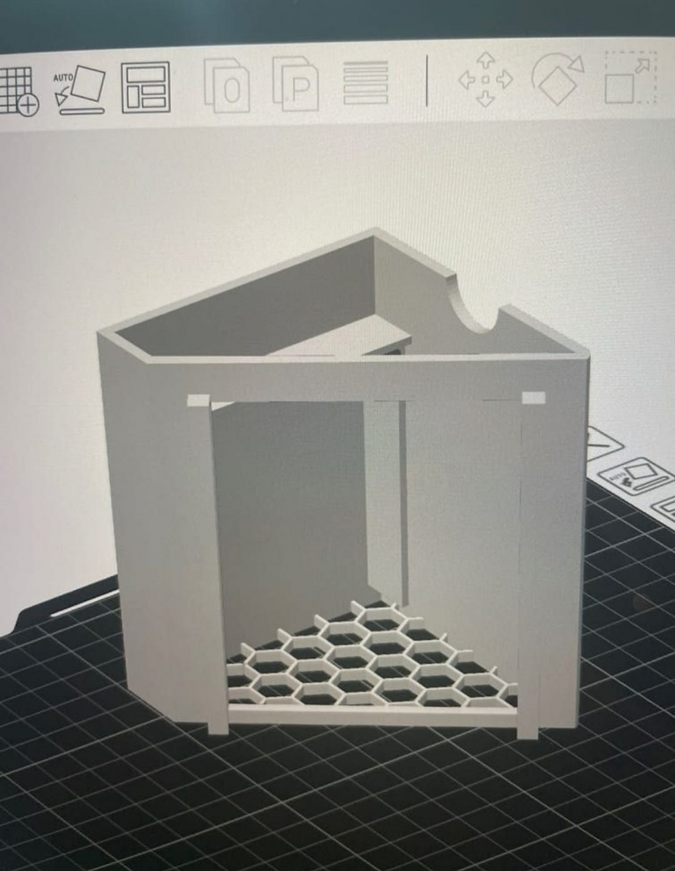 |
The finishing surface is somehow not consistent as the printer run out of filament and the hexagon shapes some of it is not properly printed out due to our F3D files. | 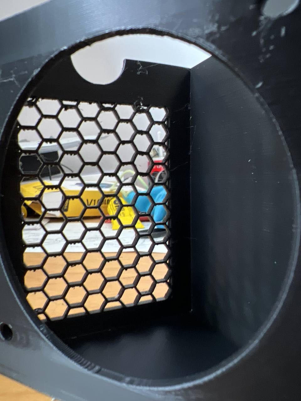 |
For Laser Cutting:
We were able to utilize our learning from the competency test in laser cutting and do it here for our prototype and I became liking to do fabrication more as it is fun and enjoyable:
For Combining of Codes
Lastly, I was tasked to combine the servo code with the Asraf code without the servo. Honestly, it takes me half a day to complete it as I struggle for a while and asraf helps me find out that the screw makes a difference with the directions that it starts.
Servo Codes | Fume Extractor Codes |
|---|---|
#include <Servo.h>
Servo myservo; // create servo object to control a servo
// twelve servo objects can be created on most boards
int pos = 0; // variable to store the servo position
void setup() {
myservo.attach(9); // attaches the servo on pin 9 to the servo object
}
void loop() {
for (pos =0; pos <=0 ; pos +=180) // goes from 0 degrees to 180 degrees
// in steps of 1 degree
Servo1.write(pos); // tell servo to go to position in variable 'pos'
delay(15); // waits 15 ms for the servo to reach the position
}
for (pos = 180; pos >= 0; pos -= 0) // goes from 180 degrees to 0 degrees
Servo1.write(pos); // tell servo to go to position in variable 'pos'
}
delay(15); // waits 15 ms for the servo to reach the position
} | // Copy this code to Arduino Studio
//
// ScienceGully
int smokeA0=A0;
int led =13;
float sensorValue;
void setup() {
pinMode(LED_BUILTIN,OUTPUT);
pinMode(smokeA0,INPUT);
Serial.begin(9600); // sets the serial port to 9600
Serial.println("Gas sensor warming up!");
delay(200); // allow the MQ-6 to warm up
pinMode(LED_BUILTIN, OUTPUT);
}
void loop() {
sensorValue=analogRead(smokeA0);
if(sensorValue > 200)
{
Serial.print(" |Smoke detected!");
digitalWrite(LED_BUILTIN, HIGH); // turn the LED on (HIGH is the voltage level)
}
else
{
Serial.print(" |Smoke not detected!");
digitalWrite(LED_BUILTIN, LOW); // turn the LED off by making the voltage LOW
}
delay(200); // wait 2s for next reading
} |
Final Code | How to Combine? |
|---|---|
#include <Servo.h>
// Declare the Servo pin
int servoPin = 3;
// Create a servo object
Servo Servo1;
int pos = 0; // variable to store the servo position
int smokeA0=A0;
int led =13;
float sensorValue;
void setup() {
// We need to attach the servo to the used pin number
Servo1.attach(9); // attaches the servo on pin 9 to the servo object
pinMode(LED_BUILTIN,OUTPUT);
pinMode(smokeA0,INPUT);
Serial.begin(9600); // sets the serial port to 9600
Serial.println("Gas sensor warming up!");
delay(200); // allow the MQ-6 to warm up
pinMode(LED_BUILTIN, OUTPUT);
}
void loop(){
sensorValue=analogRead(smokeA0);
if(sensorValue > 420)
{
Serial.print(" |Smoke detected!");
digitalWrite(LED_BUILTIN, HIGH); // turn the LED on (HIGH is the voltage level)
for (pos =0; pos <=0 ; pos +=180) // goes from 0 degrees to 180 degrees
// in steps of 1 degree
Servo1.write(pos); // tell servo to go to position in variable 'pos'
}
else
{
Serial.print(" |Smoke not detected!");
digitalWrite(LED_BUILTIN, LOW); // turn the LED off by making the voltage LOW
for (pos = 180; pos >= 0; pos -= 0) // goes from 0 degrees to 0 degrees
Servo1.write(pos); // tell servo to go to position in variable 'pos'
}
delay(20); // wait 2s for next reading
} |
|
For doing video
I did 3 videos (one is on top) with all different types of software like canvas and it takes me around 1 day plus to complete it is tough but is worth it:
Part 1: Hero Shot | Part 2: Skit | Part 3: Process Design |
|---|---|---|
Part 3. Design and Build of Part C (done by Eshvin). Link it to Eshvin’s blog
Part 4. Programming of motor and LCD (done by Insyirah). Link it to Insyirah’s blog
4. Problems and solutions
In this section, I will describe the problems encountered in the design and build process and how the team solved them.
Problems | Solutions |
|---|---|
The hole for MQ2 Smoke LPG CO Sensor Module was too tight  | We have to keep sanding the 3D frame for the MQ2 Smoke LPG CO Sensor Module slot till it is able to fit it nicely. I purposely make it smaller than the MQ2 Smoke LPG CO Sensor Module size because I was scared that if it is too big we need to re-print the whole thing but if it is too small or too tight we are able to sand it off. The only trade-off is that it will take time to do so.  |
The side with the hexagonal grid was too small for the wire to fit through  | We trim off part of the hexagonal shape and sand it till smooth, so that is hard to be noticeable from far. |
Exhaust fan placement – Originally, we wanted to put it inside  | The reason for putting the exhaust fan inside of the frame is so that it won’t have anything protruding upwards because it will look ugly. But when we try to fit it inside, I didn’t take into consideration the inner height. So, we have no choice but to place the fan outside but it turns out nice because the whole print was black and our exhaust fan was black and it create this nice illusion that forms a single piece.  |
Servo – We assumed that our exhaust fan was a mechanism  | We thought that our exhaust fan was actually a mechanism because we did some research online and ask some seniors but after clarifying with Mr. Ting apparently it is not. So, we have to figure out a way to install a servo into the prototype but we didn’t want to change anything to the design. The easiest solution that came to my mind was using a servo as a signal to indicate that the fan is on or off. So, we attach a flag to the servo and place it at the side. And it works.  |
5. Project Design Files as downloadable files
In this section, I will provide all the design files (Fusion360 files, .dxf files, .stl files, and Arduino programs files) as downloadable files.
CPDD Final files:
6. Below is my Learning Reflection on the overall Project Development.
Overall, this Project Development was an eye-opening experience for most of us as many of us as it is all first timer in fabrication unless they take D&T which is somewhat similar. However, for me, I feel that my elective and this module pull my hands-on skills better. Without Mr. Ting's guidance, I think me and asraf would be lost in this module for the report part as we are very weak in our report, and thanks to his help it help us a lot.
Nevertheless, the prototyping of the fume extractor was fun as we get to explore different types of fumes like cigarette
, soldering, and alcohol swap and test which one sense the faster and whether or fan will be a suction device to suck in all the fumes from spreading to the surrounding air. Not only do we have a suction device we also have a mechanism device which is the servo that it used for the flag when it detects fume it will rise up immediately. One fun fact at first, we thought our screw and fan is a mechanism as we search from internet and asraf ask his seniors but unfortunately it is not, therefore, we utilize servo.
Thanks to my team members we did it and we survive CPDD together as one. All the best for your FYP next semester and I feel that we have done very well in this prototype as it is very well executed.


Comments